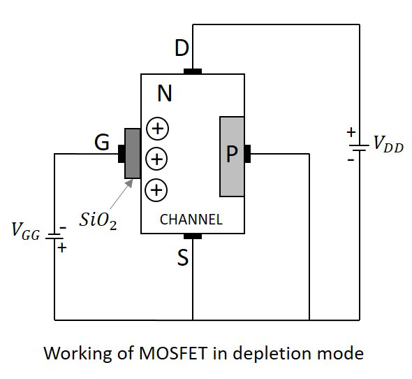
Infineon's OptiMOS™ N-channel power MOSFETs were developed to increase efficiency, power density and cost-effectiveness. Designed for high-performance applications and optimized for high switching frequencies, OptiMOS™ products offer the industry's best figure of merit. N-channel FET In an n-channel 'depletion-mode' device, a negative gate-to-source voltage causes a depletion region to expand in width and encroach on the channel from the sides, narrowing the channel.
FemtoFET™ N-Channel MOSFET transistors are the smallest, low on-resistance Power MOSFETs available in the marketplace today. The FemtoFET is Land Grid Array (LGA) package, which is a silicon Chip Scale Package with metal pads instead of solder balls. The FemtoFET is ideal for mobile handsets, tablets, and any other application where saving board space and extending battery life are required.
Featured products
CSD13380F3
12 V N-Channel FemtoFET MOSFET
CSD17585F5
30 V N-Channel FemtoFET MOSFET
CSD23280F3

12 V P-Channel FemtoFET MOSFET
CSD25485F5
12-V, P-Channel FemtoFET MOSFET
N Channel Fet Operation
Technical documenation

FemtoFET Surface Mount Guide (Rev. D)
Texas Instrument (TI) is facilitating the electronics industry’s drive towards smaller packaging outline technologies with the FemtoFET™ series of packages.
In this video product marketing engineer, Rich Nowakowski, discusses a family of FemtoFET MOSFETs, which are the industry's smallest, low on-resistance power MOSFETs available in the marketplace today.

difference between n-channel FET vs p-channel FET
This page on n-channel FET vs p-channel FET mentions difference between n-channel FET and p-channel FET.
Following section compares both FET types with respect to their features, symbol and construction.
n-channel FET
As shown in figure-1, n-channel FET is constructed using a bar of N-type material into which a pair ofP-type regions are diffused. Fig-1 also mentions circuit symbol of n-channel FET.
N Channel Fet Circuit
Following are the features of N-channel Junction FET(JFET):
• Current carriers are electrons in n-channel FET.
• Mobility of electrons is large.
• Input noise is low.
• Trans-conductance is large.
N Channel Fet Working
p-channel FET
Similar to n-channel FET, p-channel FET is constucted using a bar of P-type material into which a pair ofN-type regions are diffused. Fig-2 mentions circuit symbol of p-channel FET.
Following are the features of P-channel Junction FET(JFET):
• Current carriers are holes in p-channel FET.
• Mobility of holes is poor.
• Input noise is large.
• Trans-conductance is small.
From the comparison between n-channel FET and p-channel FET it isimperative that n-channel FET serves better than p-channel FET.
What is difference between
BJT vs FET
Diac vs Triac
JUGFET vs MOSFET
LED vs Laser
Photo Diode vs Photo Transistor
Halfwave rectifier vs Fullwave rectifier
RF and Wireless Terminologies
Share this page
Translate this page
